RK-SPI-NOR-Chainloader
Flash SPI NOR safely
This guide installs the board-qualified RK3568 chainloader into SPI NOR so the BootROM can start BL31 and U-Boot without an SD card or USB host. U-Boot then follows the selected board’s manifest-defined local and network OS search order.
The guarded installer supports only these explicitly described boards:
- Radxa ROCK 3A, selected as
BOARD=rock3a. - Youyeetoo YY3568, selected as
BOARD=yy3568.
!!! danger SPI NOR is persistent and has higher BootROM priority than eMMC, SD, and ordinary USB fallback. Use only the guarded commands below. They require a complete backup and verify every written byte before reset.
Do not substitute raw `rkdeveloptool wl` commands and do not run
`rkdeveloptool ef`. Those operations bypass this project's board,
capacity, backup, and readback protections.
Before you start
You need:
- A supported board with a populated JEDEC-compatible SPI NOR.
- A Linux programming host with
xrockandrkdeveloptoolbuilt at the pinned commits documented in Prepare a Linux programming host. - The correct recovery control and USB OTG connection for the selected board.
- An absolute, new or empty backup directory on storage other than the target board.
- UART2 access at 1,500,000 baud, 8N1 for boot evidence.
- If the goal is OS boot, an NVMe device already prepared for extlinux,
boot.scr, orEFI/BOOT/BOOTAA64.EFI.
Confirm the host tools before connecting the board:
command -v xrock
command -v rkdeveloptool
rkdeveloptool -h | grep ChangeStorage
The expected build flow and automatic OS discovery are described in the RK356x chainloading guide. SPI NOR contains only the first stage, BL31, and U-Boot; it does not contain Linux or a root filesystem.
1. Build and validate the SPI image
For ROCK 3A:
make chainload BOARD=rock3a -j"$(nproc)"
make chainload-check BOARD=rock3a
The important outputs are:
uboot_rock3a_spi.img
uboot_rock3a.bin
rock3a-u-boot.itb
For YY3568:
make chainload BOARD=yy3568 -j"$(nproc)"
make chainload-check BOARD=yy3568
The corresponding outputs are:
uboot_yy3568_spi.img
uboot_yy3568.bin
yy3568-u-boot.itb
Do not rename or exchange artifacts between boards. The generated image, memory policy, U-Boot configuration, and recovery metadata are board-scoped.
2. Enter MaskROM mode
Power the board off before changing jumpers or connecting the recovery cable. Remove removable boot media that could make diagnosis ambiguous.
ROCK 3A physical connection
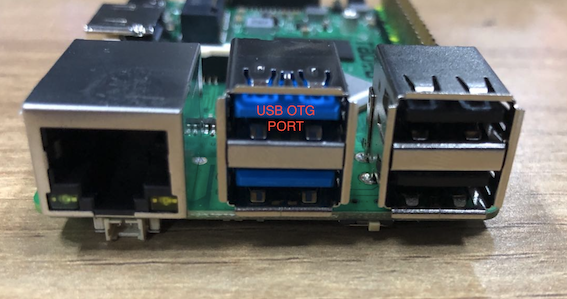
Use the upper blue USB 3 connector as the ROCK 3A USB OTG port. The reference procedure uses a USB-A male-to-male cable; connect the other end to the Linux host.
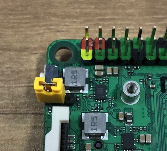
With power removed, fit the SPI-disable/MaskROM jumper shown below. Power the board, then remove the jumper after MaskROM enumeration. Do not short any other pins.
YY3568 physical connection
Use the YY3568 recovery/MaskROM control and its documented USB OTG connector. The ROCK 3A photos above do not describe YY3568 headers or connector wiring.
Confirm enumeration
On the Linux host:
rkdeveloptool ld
There must be exactly one device in MaskROM mode, similar to:
Vid=0x2207 Pid=0x350a Mode=Maskrom
If valid SPI firmware is already installed, the BootROM normally selects it before eMMC, SD, or USB. Use the board’s hardware recovery control to force MaskROM instead of relying on normal USB fallback.
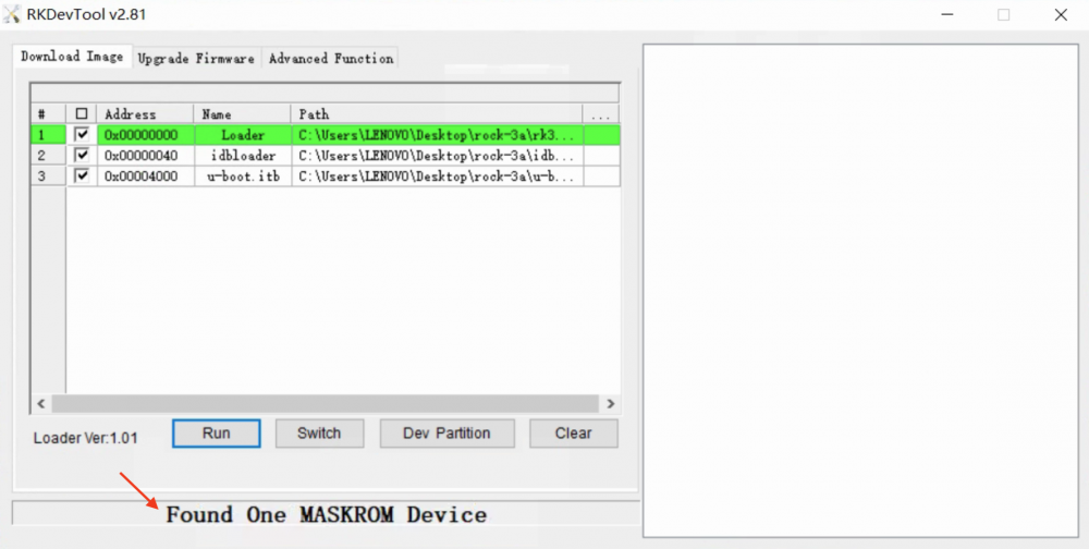
The screenshot below is only a visual reference for the Found One MASKROM
Device state in Rockchip’s Windows utility. This project does not provide a
guarded Windows flashing procedure; perform all writes from the Linux host.
3. Flash with a complete backup
The backup path must be absolute, new or empty, and have enough free space for the complete detected SPI NOR.
For ROCK 3A:
make flash-chainload \
  BOARD=rock3a \
  MEDIA=spi-nor \
  BACKUP_DIR=/absolute/path/rock3a-spi-backup \
  CONFIRM=rock3a:spi-nor
For YY3568:
make flash-chainload \
  BOARD=yy3568 \
  MEDIA=spi-nor \
  BACKUP_DIR=/absolute/path/yy3568-spi-backup \
  CONFIRM=yy3568:spi-nor
From a release archive, invoke the packaged installer directly with the same board-qualified policy. For example:
./install/flash-chainload.sh flash rock3a spi-nor \
  /absolute/path/rock3a-spi-backup rock3a:spi-nor
The installer performs these operations in order:
- Requires exactly one RK356x USB device.
- Loads the manifest-selected DDR and USB-plug helpers into RAM.
- Selects SPI NOR with
rkdeveloptool cs 9. - Validates the JEDEC identity and detected capacity.
- Backs up the complete chip as
complete-spi-nor.bin. - Writes only the required
uboot_<board>_spi.imgrange at LBA0x40(byte offset0x8000), preserving SPI sectors 0-63. - Reads the written range back and requires an exact byte-for-byte match.
- Resets only after verification succeeds.
Keep backup.json, complete-spi-nor.bin, the range backups, and
SHA256SUMS together. If verification fails, the device stays in loader mode
and the installer prints the exact restore command.
4. Verify the boot source and NVMe search
Connect UART2 at 1,500,000 baud, 8N1 before resetting. A successful BootROM handoff from SPI NOR begins with first-stage evidence containing:
source=spi-nor
YY3568 U-Boot provides a three-second interruption window and then searches:
removable SD -> NVMe -> eMMC -> SCSI -> USB -> PXE -> DHCP
If U-Boot starts but does not find the operating system, interrupt autoboot and inspect the NVMe path:
pci enum
nvme scan
nvme info
part list nvme 0
That is an NVMe discovery or boot-content problem, not an SPI programming failure. See U-Boot automatic OS discovery for the accepted boot layouts.
Restore the original SPI contents
Force the same board back into MaskROM, attach exactly one RK356x device, and
use the board and medium recorded in backup.json. For example:
make restore-chainload \
  BACKUP=/absolute/path/rock3a-spi-backup \
  CONFIRM=restore:rock3a:spi-nor
For YY3568, use its own backup directory and
CONFIRM=restore:yy3568:spi-nor. Restoration rejects mismatched board names,
media, manifest hashes, capacities, or saved ranges. Never restore one board’s
backup onto another board.
After restoring ROCK 3A SPI and resetting, remove the recovery jumper. A restored or blank SPI permits the BootROM to continue to its lower-priority media.
Image attribution
The three photographs and screenshots on this page are adapted from Radxa’s
Install the image to SPI Nor Flash
guide. Copyright Radxa Computer (Shenzhen). They are redistributed under the
Creative Commons Attribution 3.0 Unported
License. Exact source URLs,
dimensions, byte sizes, and SHA-256 hashes are recorded beside the local
assets in SOURCES.txt.